Product Supply Code: NLAB-VOCATIONALTVET26002
Product Name: ABS System Trainer
Tender Supply Category: Automotive Mechanical Training Lab
ABS System Trainer
Manufacturers and Suppliers India
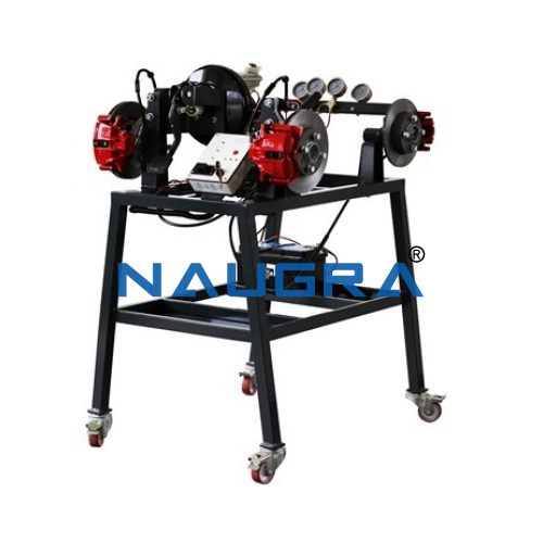
A complete, fully operational, ABS unit which is typically found on passenger vehicles.
• Four variable speed electrical drive system for each wheel to control the individual speed of each wheel
• Master brake cylinder with pedal handle
Linear Heat Conduction System
• ABS hydraulic actuator (modulator) unit which is controlled by the onboard computer system (ECU)
• Five brake line pressure gauge to show the pressure differentials from the meter brake cylinder to the individual wheels
• Brake master cylinder with vacuum assist boost mechanism and brake pedal assembly.
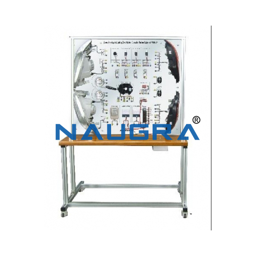
• The front of the trainer features precise schematic color graphic illustrations that clearly explain the operation of the entire ABS and braking system.
• A control Panel should be provided with an on/off power switch, power system light (POWER ON), ABS warning light (indicated problems) and an ABS operational light (ABS ON). Also has Volt and Ampere meters to measure the DC input power and a brake light to show the operation of the braking system just as on the vehicle.
• Road Conditions and Performance Display Panel.
• The trainer is supplied complete with a training course on ABS operation and servicing including student job sheets and a technical manual on ABS systems
Modules:
• The trainer should be developed not only to be just a simulator but the ABS system is fully functional, featuring a real ABS unit and real brake systems which makes it ideal for student observation, experimentation and also troubleshooting.
• Different friction values can be set for each wheel to simulate variable road conditions.
• Control of the braking action could be observed with either the ABS unit on or off.
• ABS unit is clearly laid out on a display board that is mounted on a mobile trolley.
Electronic/Electrical Fault Insertion System:
• Multiple electronic fault insertion system: This system should allow for up to 10 faults to be inserted at any one time. Faults can be inserted individually or in groups.
• Electronic Fault Panel: Faults indicated by LEDs. When the fault is electronically activated a corresponding LED will illuminate showing the fault is active.
• Student Testing Mode: The LED fault indication display can be deactivated so that the faults can be active but the display is switched off.
• Electronic Fault Reset Button: The LED control should have a fault-reset button that will clear and reset the system back to normal.
• Test Points: The trainer has short circuit protected test points that allow the student to take measurements during the troubleshooting exercises.
Included Accessories:
• Vacuum pump for power brake boost
• Fault system with 10 electrical faults and Electrical Test point
| Power supply | 30A, 12 VDC regulated power supply |
| Pump | Vacuum pump for power brake boost |
| No of wheels | Four rotating wheels with wheel sensors |
| Cylinder | Master brake cylinder with pedal handle |
ABS System Trainer Quality Assurance: We being a leading ABS System Trainer manufacturer from India. NaugraLabEquipments are actively involved in providing precision equipments of premium quality to clients across the globe for Testing Lab and TVET Technical Lab, Industial Training Institutions. We always utilize the most advanced and sophisticated technology for production process of ABS System Trainer and supply exceptional range of other products like ABS System Trainer for tender supply from India.
We supply ABS System Trainer for Bidding and Tendering Turnkey Projects. We supply all laboratory products related to Ministry of Education and Ministry of Health, Medical and Hospital Lab Tenders, Material Testing Lab, School Science Scientific Instruments, Lab Teaching and Educational Lab Equipments, TVET Technical and Vocational Education Training Lab. Manufacturers of ABS System Trainer from India.
Supply of ABS System Trainer from India to Finland, France, Tanzania, Thailand, Sri Lanka, Congo, Costa Rica, Ivory Coast, Croatia, Cuba, Cyprus, Czech Republic, Denmark, Djibouti, Dominica, Afghanistan, Albania, Algeria, Andorra, Angola, Antigua and Barbuda, Argentina, Armenia, Australia, Austria, Azerbaijan, Bahamas, Bahrain, Bangladesh, Barbados, United Arab Emirates (UAE, Dubai), United Kingdom (London), United States, Uruguay, Uzbekistan, Vanuatu, Belarus, Belgium, Belize, Benin, Bhutan, Bolivia, Bosnia and Herzegovina, Botswana, Brazil, Brunei, Bulgaria, Burkina Faso, Burma Myanmar, East Timor, Ecuador, Egypt, El Salvador, Equatorial Guinea, Eritrea, Estonia, Ethiopia (Addis Ababa), Fiji, Burundi, Cambodia, Cameroon, Canada, Cape Verde, Central African Republic, Chad, Chile, Colombia. ABS System Trainer suppliers in Luxembourg, Macedonia, Madagascar, Malawi (Lilongwe), Malaysia (Kuala Lumpur), Maldives, Mali, Malta, Marshall Islands, Mauritania, Mexico, Micronesia, Moldova, Monaco, Mongolia, Montenegro, Morocco, Mozambique, Namibia, Comoros, Congo. ABS System Trainer manufacturers in Dominican Republic, Gabon, Gambia, Georgia, Germany, Ghana, Greece, Grenada, Guatemala, Guinea, Guinea-Bissau, Guyana, Haiti, Honduras, Hungary, Iceland, Indonesia, Iran, Iraq, Niger, Nigeria (Abuja), Norway, Oman, Palau, Panama, Papua New Guinea, Paraguay, Peru, Philippines (Manila), Poland, Ireland, Israel, Italy, Jamaica, Japan, Jordan, Kazakhstan, Kenya (Nairobi), Kiribati, Korea, Kuwait, Kyrgyzstan, Laos, Latvia, Lebanon, Lesotho, Liberia, Liechtenstein, Lithuania, Mauritius, Nauru, Nepal, Netherlands, New Zealand, Nicaragua, Portugal, Qatar, Romania, Russia, Rwanda (Kigali). ABS System Trainer exportets to Saint Kitts and Nevis, Saint Lucia, Saint Vincent and the Grenadines, Samoa, San Marino, Sao Tome and Principe, Saudi Arabia, Senegal, Serbia, Seychelles, Sierra Leone, Singapore, Slovakia, Slovenia, Solomon Islands, Somalia, South Africa, South Sudan, Spain, Sudan, Suriname, Swaziland, Sweden, Switzerland, Syria, Tajikistan, Togo, Tonga, Trinidad and Tobago, Tunisia, Turkey, Turkmenistan, Tuvalu, Uganda (Kampala), Ukraine, Venezuela, Vietnam, Yemen , Zambia (Lusaka), Zimbabwe