Product Supply Code: CE995
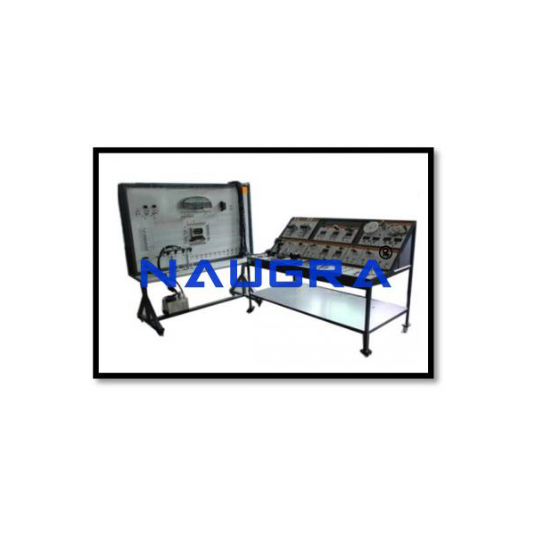
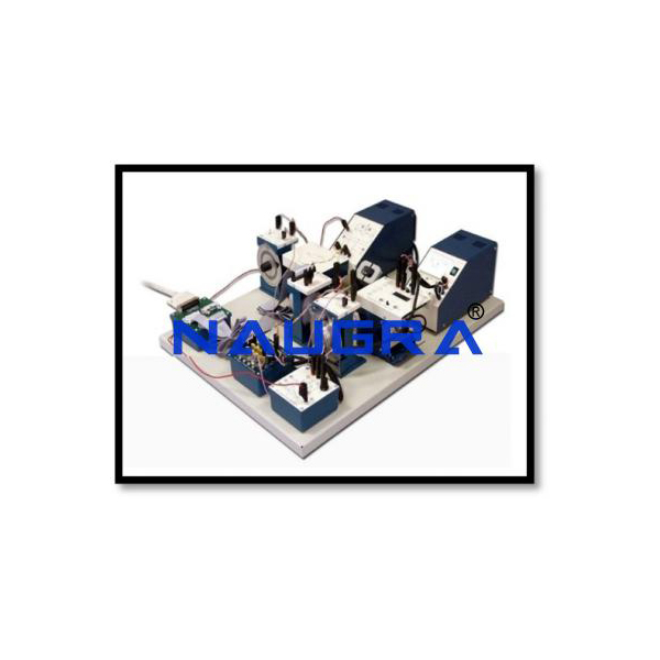
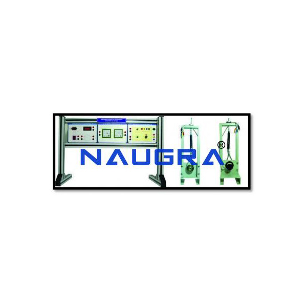
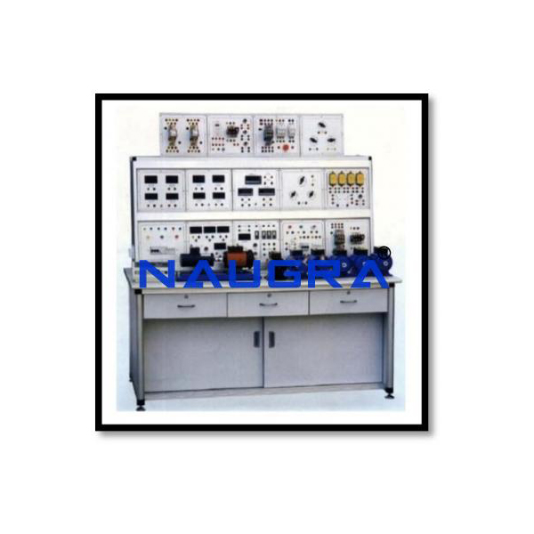
Product Name: Complete Experiment Setup For Electrical Machines And Drive
Tender Supply Category: Industrial Control and Instrumentation Engineering Stream Lab
Complete Experiment Setup For Electrical Machines And Drive
Manufacturers and Suppliers IndiaComplete Experiment Setup For Electrical Machines And Drive Complete system for training in electrical machines (DC, AC, Three-Phase and Synchronous), as well as industrial frequency converters with minimally the following characteristics: Topics: Fundamentals Of Three-Phase Machines Equivalent Circuit For An Asynchronous (Induction) Motor Torque, Efficiency And Optimum Magnetisation Circuit Wiring And Connection Of Components Setting Up A Drive And Testing Its Operation Parameter Setting For A Frequency Converter Learning The Key Menus Measurement Of Converter Output Voltage Effect Of Start Voltage Effect Of Start Compensation (Lxr Compensation) Response Of The Machine In The Absence Of Starting Voltage And Compensation Effect Of Slip Compensation Recording Of V/F Characteristic For A Machine Operating Without A Load, With And Without Compensation Of The Frequency Converter Design And Function Of Dc Machines Armature Reaction And Commutation Series-Wound Machines Possibilities For Changing Speed Energy Conversion Shunt-Wound Machines Operation At Constant Speed Self-Excitation Current-Voltage Characteristics Load Characteristics Possibilities For Changing Speed And Adjusting For Load Starting And Braking Characteristics Of Generators Power Performance Connection And Operation Of Ac Machines Reversing Direction Of Rotation Measurement Of Efficiency Characteristics Of Motors Load Characteristics Non-Salient-Pole And Salient-Pole Rotors Voltage Equations Equivalent Circuit And Vector Diagram Operation With No-Load And With A Permanent ThreePole Short-Circuit Locus Diagrams And Control Characteristics Torque And Loading Potier Diagram And Armature Reaction Synchronisation And Use Of Multiple Machines In Parallel Starting Methods For Synchronous Motors Control Of Reactive Power Power Performance Voltage Generation Excitation Of Synchronous Machines Operating Response Armature Current And Torque Braking Operation And Locus Diagrams Starting And Synchronisation Single-Phase Generators Design And Function of induction machines Characteristics On Motor Operation Starting Star-Delta Starting Stator Resistance Starting Circuit Braking Power Performance Of An Ideal Rotating Field Machine Power Flux Open-Circuit Experiment Short-Circuit Load Experiment Fundamentals Of Three-Phase Generators Characteristics In Generator Operation Generator Slip Self-Excitation Of An Asynchronous Generator Voltage Stability Operation In A Constant-Voltage, Constant Frequency System Insular Operation Power Performance The system come with full experimental guide, with many tasks to be executed both in printed version and with a virtual environment (software do manage manuals). Pdf files only will not be accepted, the software contain teacher and student environments (with and without answers) and interactive specialized application to be used in the classes. It is compatible with an additionally supplied online portal for the management of experiments and devices, with School license for any number of users to manage, structure and inventory a complete scientific or technical educational resource collection to optimize the preparation and follow up times of the lesson. The online portal is platform independent and responsive and runs on all current Internet-enabled devices. Overview of the total inventory of the educational resource collection, e.g. with number, article name, inventory number, storage location. Overview of all experiments possible with the collection of educational materials or a special device. Installation and management of the individual storage structure such as premises, cabinets, shelves and trays, also with deposited images. Inventory of the complete teaching material collection with indication of the storage location. Inventory of device sets, which in turn consist of several individual devices. Inventory also using internal school inventory numbers or with individual barcodes, also for distinguishing identically constructed devices. Inventory also indicating the availability of a device, e.g. available, borrowed, defective. Generation of individual barcodes for label printing. Support of standard barcode scanners, tablets and smartphones for automated access to devices. Administration also of own articles or articles of foreign manufacturers, including description, pictures, documents, media and comments. Import of existing inventory lists. Access to instruction sheets, safety data sheets and other media - expandable with your own documents. Optionally extensible (paid) for online access to various experiment literature. Creation and documentation of own experiments with corresponding hints, pictures and comments. Creation and export of inventory lists with indication of number, article name, storage location, status, inventory numbers and comments, e.g. in Excel or LibreOffice. Creation and export of experiment lists, which are feasible with the collection of teaching aids taking into account the availability of the individual devices, e.g. in Excel or LibreOffice. Creation of the device lists of an experiment with the indication of number, article description and storage location, e.g. as PDF for printout. Creation of an up-to-date list of hazardous substances with designation, danger symbols and storage location of the hazardous substance Each system is composed minimally by the following components: 1 Coupling Rubber coupling sleeve for mechanical connection of two electrical machines of the 0.1 or 0.3 kW series. 1 Electrical machines test bench with software Equipment set for recording the characteristics o electrical machines of the 1 kW class in all four quadrants, consisting of: Electrical dynamometer Control unit Electrical dynamometer A pendulum ball bearing squirrel cage motor with integrated incremental encoder for speed detection and a visible torque sensor. This machine can drive all machines of 1 kW class or decelerate down to standstill. The power is supplied by the control unit via a fixed connection cable with 7-pin circular connectors; the signal is transmitted via a fixed connection cable with D-Sub 25 connector. The three-phase pendulum machine is built on an aluminium base with slides that can be placed on the supplied with aluminium bed with locking system. For calibration of the torque measurement, a balance weight is fixed to the pendulum machine. With a lever and a 2 kg weight, the measuring system can be adjusted. Control unit Microcontroller equipped device with integrated frequency converter for the power supply and control of the cradle-type three-phase asynchronous machine. Display of speed and torque of the machine under test. Manual and automatic recording of the characteristics in all four quadrants of the speed/torque plane. Connection to the PC via USB port. Technical Data‟s: Automatic digital speed control: ±5000 rpm Automatic digital torque control: ±30.0 Nm Automatic recording of run-up and load characteristics Load simulations: flywheel, freely adjustable fan drive (M~ kn2) freely adjustable winding drive (M~ k/n), lift drive (constant torque) Characteristics recorded in accordance with user specifications (Mi=ni) External control: ±10 V Seven-segment display, 25 mm high Speed: 4 digits Torque: 3 digits Parallel operation is possible with the help of the software Temperature monitoring: Machine under test Cradle type three-phase asynchronous machine Control unit Shaft guard monitoring: system shut-down with protection for unintended system start Four quadrant display with LEDs for operating mode of the machine under test Adjustable torque limiting (overload protection) and stop speed (for automatic characteristic recording) RMS measurement: three inputs for voltage measurement (Vmax=600 V AC/DC), one input for current measuring (Imax=10 A AC/DC), all suitable for frequency converter USB connection for transmission of measured values and remote control via software CBM 10 Highest security standards: leakage current <5 mA Power supply: 230 V, 47 ... 62 Hz, 2,3 kW Scope of delivery: Mains lead with earth-contact plug Demo version of software CBM 10 USB cable, 3 m 25-pole connecting cable Supply cable for cradle-type machine Mass 2 kg Cylindrical bar Machine ground base Coupling and schaft end guard transparent Includes software with the following characteristics: Software for recording and evaluating measurement data acquired via Three phase high power measurement device, with comprehensive integrated help functionality and many operable experiment examples. Including measurement server for the distribution of live measurements, table and diagram as well as measurement files on tablets or smartphones. School license for use on any number of PCs in a school or institute Supports up to 8 measurement devices, via USB-ports Supports Joule and Wattmeter and Universal Measuring Instrument Supports sensor boxes Additionally supports numerous devices via th serial interface (e.g. Video Camera IRPD, balance) Connection to the integrated measurement server in the local network via QR code - "Plug and play" enabled for easy use: the software automatically detects the connected devices and sensor boxes and displays these graphically, inputs and outputs are activated simply by pointing and clicking and typical experiment parameters are automatically loaded (depending on the connected sensor box) - Measurement data can be displayed in the form of analog/digital instruments, tables and/or diagrams (also simultaneously, with user definable axis assignment) Measured values can be recorded manually (at keystroke) or automatically (choice of time interval, measured time, lead time, trigger or additional measurement condition) Powerful evaluation functions including various fits (straight line, parabola, hyperbola, exponential function, free fitting), integrals, diagram labeling, calculation of user-definable formulas, differentiation, integration, Fourier transforms Experiment files in XML-data format Convenient exporting of measurement data and diagrams via the clipboard "Logbook" function lets you briefly document other experiment information in the experiment file Complete with more than 150 experiment examples from physics, chemistry and biology with detailed descriptions Graphical display, sensor box and connector allocation when the experiment file is loaded - Free updates and demo version available through our internet homepage The software support vector diagrams (real time) and plot angles The software CD contains two Windows programs in german and english, one for the recording of characteristics of electrical machines and one for the control of the modular frequency converter. School licence. Industrial Frequency Converter Didactically adapted, industrial frequency converter with voltage link for the generation of three-phase, frequency and amplitude variable output voltage from single-phase AC mains. This device can be used for speed open loop control and speed and torque closed loop control of asynchronous machines and IPM machines of the power classes 0.3 kW. Front panel with block diagram showing various functions of the inputs and outputs. Inverter control principle: U / F or DANFOSS-VVC The adaptation of the drive machine and the control devices via an extensive set of parameters. This can be easily programmed and optimized via the DANFOSS software MCT10 via the integrated USB 6 digital programmable, PLC compatible control inputs, 2 digital pulse and rotary encoder inputs 2 digital inputs STO (Save Torque Off) 2 analog inputs 0 ... 10 V and 0/4 ... 20 mA 1 analogue output 0/4 ... 20 mA (500 W 1 programmable control and relay output, status indication with LED's 1 USB port 1.1 (Full Speed) 2 PROFINET connections 3 phase connections for connecting the machine 1 protective conductor 2 connections for equipotential bonding or partial equipotential bonding Menu navigation in German, English, French, Danish, Spanish, Italian and Portuguese. Display of all important operating states (eg frequency, motor current, voltage, torque) via display Integrated speed controller Technical specifications: Output current: continuous 3 x 2.2 A (3 3.5 A max 60 s) Output power: continuous 0.9 kVA Output voltage: 3 x 0 ... 133/230 V. Output frequency: 0.2 ... 132 Hz / 1 ...200Hz Mains connection: 220 ... 240 V, 50/60 Hz Input current: max. 5.9 A Scope of delivery: Mains connection via IEC socket with mains cable, earth contact and GB version. USB cable Technical documentation and software for parameterizing and documenting the frequency inverter can be free downloaded from DANFOSS. MultiFunction Machine 0.3 Three-phase multi-function machine, can be used as slip ring motor or as synchronous machine for motor and generator operation. Machine with one shaft end is insulated built on an aluminium base with glides. The machine is to be operated on the machine bench. All connections are brought out on the overhead connection box separate on 4 mm safety plugs. The nominal ratings are mounted on three rating plates on the connection box The machine is protected by a built-in stator winding temperature switch against overload. In addition to th protective conductor connection attachment for potential equalization line via M6 thread on the connection box is also provided. Ratings for operation as slip ring motor: Power: 0.27 kW Voltage: 230/400 V Δ/Y Current: 1.44/0.83 A Frequency: 50 Hz Power factor: 0.7 Design: 4 pole Speed: 1360 min-1 Ratings for operation as synchronous motor Power: 0.27 kW Voltage: 230/400 V Δ/Y Current: 0.9/0.52 A Excitation voltage: 20 V Excitation current: 4 A Frequency: 50 Hz Power factor: 1 Design: 4 pole Speed: 1500 min-1 Squirrel Cage Motor 400/690/0.3 Squirrel Cage Motor 400/690/0.3Three-phase asynchronous motor with squirrel cage rotor.Machine with one shaft end is insulated built on an aluminium base with glides. The machine is to be operated on the machine bench. All connections are brought out on the overhead connection box separated on 4 mm safety plugs. The nominal ratings are mounted on three rating plates on the connection box. The machine is protected by a built-in stator winding temperature switch against overload. In addition to the protective conductor connection attachment for potential equalization line via M6 thread on the connection box is also provided. Ratings: Motor: Power Class: 0.3 Power: 0.25 kW Voltage: 692/400 V Δ/Y Current: 045/0.77 A Frequency: 50 Hz Power factor: 0.70 Design: 4 pole Speed: 1350 min-1 Generator: Not specified Mechanical data‟s: Type of construction: B3 Schaftend: 1 Base: Aluminium Connection box: Top Temperature class: B (120°) Degree of protection Squirrel Cage Motor D 0.3 Squirrel Cage Motor D 0.3Three-phase asynchronous motor with squirrel cage rotor, Dahlander circuit, pole changeable. Machine wit one shaft end is insulated built on an aluminium base with glides. The machine is to be operated on the machine bench. All connections are brought out on the overhead connection box separated on 4 mm safety plugs. The nominal ratings are mounted on three rating plates on the connection box. The machine is protected by a built-in stator winding temperature switch against overload. In addition to the protective conductor connection attachment for potential equalization line via M6 thread on the connection box is also provided. Ratings: Power: 0.25/0.37 kW Voltage: 400 V Δ/Y-Y Current: 1.0/1.1 A Frequency: 50 Hz Power factor: 0.62/0.75 Design: 4/2 pole Speed: 1400/2800 min-1 Squirrel Cage Motor SW 0.3 Squirrel Cage Motor SW 0.3Three-phase asynchronous motor with squirrel cage rotor, 2 separate windings, pole changeable. Machine with one shaft end is insulated built on an aluminium base with glides. The machine is to be operated on the machine bench. All connections are brought out on the overhead connection box separated on 4 mm safety plugs. The nominal ratings are mounted on three rating plates on the connection box. The machine is protected by a built-in stator winding temperature switch against overload. In addition to the protective conductor connection attachment for potential equalization line via M6 thread on the connection box is also provided. Ratings: Power: 0.11/0.20 kW Voltage: 400 V Y/Y Current: 0.6/0.7 A Frequency: 50 Hz Power factor: 0.71/0.72 Type: 6/2 pole Speed: 880/1390 min-1 Capacitor Motor R 0.3 Capacitor motor R 0.3 Single-phase AC motor with starting relay, starting and operating capacitor. Machine with one shaft end is insulate built on an aluminium base with glides. The machine is to be operated on the machine bench. • All connections are brought out on the overhead connection box separated on 4 mm safety plugs. The nominal ratings are mounted on three rating plates on the connection box. The machine is protected by a built-in stator winding temperature switch against overload. In addition to the protective conductor connection attachment for potential equalization line via M6 thread on the connection box is also provided. Motor: Power: 0.37 kW Voltage: 230 V Current: 2.6 A Frequency: 50 Hz Power factor: 0.93 Starting capacitor CA: 50-63 µF Operating capacitor CB: 20 µF Design: 4-pole Speed: 1400 rpm Generator: Not specified 1 Rotor Starter 0.3 Three resistors, synchronously adjustable in 6 steps, for slip ring motor and multifunction machine 0.3 kW. Resistance values of switch steps: 20/10/5.5/2.5/1/0 Ohm Additional fixed taps at: 10/2.5 Ohm 1 Squirrel cage fault simulator The fault simulator in conjunction with the squirrel-cage motors in the 0,3 kW and 1,0 kW power classes permits the simulation of typical malfunctions like:- Short to ground Winding breaks Turn-to-turn faults Winding-to-frame short-circuit Tripping the thermal circuit breaker The faults are generated by 14 switches arranged behind a locked cover. 1 DC Compound Machine 0.3 DC Compound Machine 0.3 DC compound machine for motor and generator operation is isolated built on an aluminium base. The machine can be used as shunt, series, or compound wound machine, series winding with tap for compounding and shunt winding. The machine is protected by a built-in stator winding temperature switch against overload. Machine with one shaft end is insulated built on an aluminium base with glides. The machine is to b operated on the machine bench. All connections are brought out on the overhead connection box separated on 4 mm safety plugs. The nominal ratings are mounted on three rating plates on the connection box. In addition to the protective conductor connection attachment for potential equalization line via M6 thread on the connectio box is alsoRatings for operation as Shunt machineMotor: Power: 0,3 kW Voltage: 220 V Current: 1,8 A Excitation voltage: 200 V - Excitation current: 0,26 A - Speed: 2000 rpmGenerator: Power: 0,22 kW Voltage: 220 V Current: 1 A Excitation Starter 0.3 Circular rheostat (Step winding) with scale 100 0 % for starting DC motors 0.3 kW. Resistance: 47 Ohm Current: 2.5 A 1 Field Regulator Motor 0.3 Circular rheostat with scale 0 - 100 % for adjusting the excitation in DC shunt and compound wound motors 0.3 kW. Resistance: 560 Ohm Current: 0.52 A 1 Field Regulator Generator 0.3 Circular rheostat with short-circuit contact and scale 0 - 100 % for adjusting the excitation in D shunt and compound wound generators 0.3 kW. Resistance: 560 Ohm Current: 0.52 A 1 EXPERIMENTAL MANUA L: Industry Invert. Drive 0.3 Book and online experiment manual to be shared by QR code: Industrial frequency converters, in german and english 1 EXPERIMENTAL MANUAL: DC Machines 0.3 Book and online experiment manual to be shared by QR code: DC Machines 0.3, in german and english 1 EXPERIMENTAL MANUAL: AC Machines 0.3 Book and online experiment manual to be shared by QR code: AC Machines 0.3, in german and english 1 EXPERIMENTAL MANUAL: 3PInduction Machine 0.3 Book and online experiment manual to be shared by QR code:: Induction Machines 0.3, in german and english 1 EXPERIMENTAL MANUAL: 3PSynchron ous Machine 0.3 Book and online experiment manual to be shared by QR code: Synchronous Machines 0.3, in german and english 1 Three phase high power measurement device with WIFI, display, tablet app and PC software The Three phase high power measurement devic is a combination of isolated and differential oscilloscope, multimeter, wattmeter, energy analyzer and recorder. It was designed in its concept for demonstration and laboratory experiments. The Three phase high power measurement device has been optimized for the following applications: Energy grids: Voltage and frequency stability Load behavior of networks Effect of harmonics Electrical machines: Inrush current of transformers and machines Ratio of transformers Efficiency of machines Power Electronics: rectifier DC / DC converter DC / AC converter frequency converter filter Three phase high power measurement device in detail: simultaneous measurement of U, I, ju, j, f and P in 4 channels Instantaneous values U, I and P Averaged values U, I and P RMS values (AC + DC) U and I RMS values (AC) U and I Fundamental wave filters Delta connection adjustment universal connection options via USB-Type C connection with PC or laptop via the WLAN option with the school network setting up your own access point automatic or manual range selection Electrical power calculation S, P, QC and QL Electrical work WS, W and WQ Resistance calculation R, Z, XC, XL, G, Y BC and BL positive sequence component, negative sequence component and zero sequence component in 3phase systems Derivative with respect to time, integral over time, FFT analysis, mean value, histogram, and model Drivers allow you to evaluate the data with LabVIEW and MATLAB Possibility of manual operation directly on the device by means of a rotary selector with cursor keys Direct reading in 9 cm, backlit display Display of up to 24 measured values in one display Display of all values for each channel Display of all values in tabular form Display of measured values in diagram Display of a vector diagram wireless connection to the tablet app via WLAN for experimenting with tablet and smartphone (iOS, Android and Windows) Measuring instrument category CATIII 300: allows the use of the measuring instrument from tests with safety extra-low voltage (SELV) via 3 phase systems with or without neutral conductor up to testing in power electronics, eg. B. DC link voltage of 700 V DC FPGA-based real-time processing in the device enables comprehensive network analysis in the three-phase networks, which are displayed directly on the device in the vector diagram Technical specifications: DISPLAY & OPERATION Graphic display: 9 cm (3.5 "), QVGA, colored, light (adjustable up to 400 cd / m²) Operation: Pushbutton and incremental encoder with pushbutton INPUTS & OUTPUTS Inputs: 4 isolated measuring channels CAT III 300, each with I and U measurement (max. 8 can be used at the same time) Input A -D: U and I connection via 4 mm safety sockets Measuring ranges U: 25/70/250/700 VAC ± 36 /± 100 / ± 360 / ± 1000 VDC Measuring ranges I: 0.7 / 1.6 / 7/16 / AAC ± 1 / 2.5 / ± 10 / ± 16 ADC Sampling rate: max. 1,000,000 values / s per channel at U and I max. 500,000 values / s GENERAL Loudspeaker: Error message when exceeding th measuring ranges Data storage: 100,000 readings for each measurement series, built-in Micro SD card (4 GB) for over a thousand measurement files and screenshots WLAN: 802.11 b / g / n as access point or client (WPA / WPA2) VNC server: integrated USB ports: Connect a USB Type C Mains voltage: 230 V 50 - 60 Hz (conversion to 115 V possible) Connected load: 50 W Dimensions: 300 mm x 300 mm x 180 mm Weight: 3.7 kg Scope of Delivery: Power cord USB A / C cord Includes software with the following characteristics: Software for recording and evaluating measurement data acquired via Three phase high power measurement device, with comprehensive integrated help functionality and many operable experiment examples. Including measurement server for the distribution of live measurements, table and diagram as well as measurement files on tablets or smartphones. School license for use on any number of PCs in a school or institute Supports up to 8 measurement devices, via USB-ports Supports Joule and Wattmeter and Universal Measuring Instrument Supports sensor boxes Additionally supports numerous devices via the serial interface (e.g. VideoCamera IRPD, balance) Connection to the integrated measurement server in the local network via QR code - "Plug and play" enabled for easy use: the software automatically detects the connected devices and sensor boxes and displays these graphically, inputs and outputs are activated simply by pointing and clicking and typical experiment parameters are automatically loaded (depending on the connected sensor box) - Measurement data can be displayed in the form of analog/digital instruments, tables and/or diagrams (also simultaneously, with userdefinable axis assignment) Measured values can be recorded manually (at keystroke) or automatically (choice of time interval, measured time, lead time, trigger or additional measurement condition) Powerful evaluation functions including various fits (straight line, parabola, hyperbola, exponential function, free fitting), integrals diagram labeling, calculation of user-definable formulas, differentiation, integration, Fourier transforms Experiment files in XML-data format Convenient exporting of measurement data and diagrams via the clipboard "Logbook" function lets you briefly document other experiment information in the experiment file Complete with more than 150 experiment examples from physics, chemistry and biology with detailed descriptions Graphical display, sensor box and connector allocation when the experiment file is loaded - Free updates and demo version available through our internet homepage 2 Digital Multimeter 3340 - Safety: EN 61010-1; CAT III 600 V - 39 mm, 3 ¾ digit LCD display; max. indication: 4000, with backlight Auto power off, Auto ranging Data hold function, Relative mode Continuity test and diode test Accessories: Test leads, Type-K- Thermocouple probe, battery and operation manual in German and EnglishDC voltage: 400 mV/4/40/400/600 V 0.1 mV; ± 0.5% + 2 dgt. AC voltage: 4/40/400/600 V - 1 mV; ± 1.2% + 3 dgt. DC current: 400 µA/4/40/400 mA/4/10 A - 0.1 µA; ± 1% + 3 dgt. AC current: 400 µA/4/40/400 mA/4/10 A - 0.1 µA; ± 1.5% + 5 dgt. Resistance: 400 Ω/4/40/400 kW/4/40 MΩ 0.1 Ω; ± 1% + 2 dgt. Capacitance: 40/400 nF/4/40/100 µF - 10 pF; ± 3% + 5 dgt. Frequency: 5/50/500 Hz/5/50/500 kHz/5 MHz - 0.001 Hz ± 1.2% + 3 dgt. Tem erature: -20°C...+760°C ± 1°C; ± 3% + 3 dgt. Operating Voltage: 9 V Battery Dimensions (W x H x D): 92 x 195 x 38 mm Weight: 380 g Three phase supply unit with RCD To switch the 3-phase supply in experiments with electrical loads for line voltages of 400 V. Cam switch 4 pole Residual Current Device, 30 mA Motor protection switch 6-10 A Phase control lamps L1, L2, L3 Mains cable with Cekon plug Adjustable transform er 0...260 V, 4 A Instrument for supply and experiments involving electrical machines and the electronics of energy technology, equipped with: Mains switch: Mains voltage: 230 V, ± 10 %, 50...60 Hz Output: 1 x 260 V / 4 A AC; Short term 5 A 1 thermomagnetic instrument safety switch 5 A (sec.) Output: 2 4-mm safety sockets with connecting leads and shock-proof plug 16 A DC engine supply 300 W Full supply appliance in a 19" casing for the constant-current characteristic of electrical machines with a constant voltage in the power category up to 0.3 kW, equipped with: Mains switch, illuminated Output: 40 - 250 v / 0 - 6 a direct current and co-current flow adjustable, stabilised, short circuit-proof, with power factor adjustment - output: ca. 200 V/6 A direct current (full-wave rectifier, depending on input voltage) Safety: appliance safety switch 6 A Technical approval: 4x4-mm safety sockets - display: 2 digital displays (letter height:12.4 mm) for indicating current and voltage - current limiting display: 1 red LED - change-over switch: U const. / U const. external, with a mode display 1 green LED - External Input for control the voltage power supply: (0 - 10 V DC) via 2 x 4-mm safety sockets - width: 63 PU 1 Resistive Load 0.3 Three synchronously adjustable circular rheostats (Step winding) with scale 100 - 0 %, each with a series resistor and fuse in the sliding-contact connection, suitable for parallel, series, star and delta circuits. Resistance: 3 x 1800 Ohm Series resistance: 3 x 47 Ohm Current: 3 x 1 A 1 Capacitiv e Load 0.3 Three groups of MP capacitors, each consisting of four capacitors, suitable for parallel, series, star and delta circuits. Capacitance: 3 x 1/2/4/8 µF, 450 V 1 Inductive Three inductances with taps at 0.2/0.4/0.6 H Load (0.65 A), 0.8/1.0/1.2 H (0.5 A) and 2.4/4.8/6.0 H (0.25 A) suitable for parallel, series, star and delta circuits. Manual Synchronisation Unit Synchronisation unit with manual switch to connect the generator to the mains. Equipped with: Two 7-segment voltage displays Two 7-segment frequency displays One 7-segment zero-volt display One optical synchronoscope Six synchronisation lamps Two control up/down indicators for voltage and frequency Two direction indicators of the rotating field One manual three pole switch On/Off Switch Three-Pole For switching of three-phase units. Technical data: Switch load: 20 A / 500 V AC Switch positions: 0 - 1 Power Circuit Breaker Module 3-phase ON/OFF switch with auxiliary contact (NC) for transmission line model 380 kV. Can b controlled manually using ON/OFF pushbutton or externally via switching contact, TTL level or 24 V DC. The switching state is indicated by LED's and is additionally available as TTL level from 4-mm sockets. Control input (switching contact, TTL level, 24 V DC) for external switch-off command (tripping on faults). Contact load capacity: 400 V AC, 3 A - Mains connection: 115/230 V, 50 Hz with mains connecting cable and earthing-pin plug Motor Protection Switch 2.4-4A Three-pole, with overload and instantaneous short-circuit trip, single-phasing sensitivity according to VDE 0660. Bimetal tripping, setting range: 2.4 - 4.0 A. Motor Protection Switch 1-1.6A Three-pole, with overload and instantaneous short-circuit trip, single-phasing sensitivity according to VDE 0660. Bimetal tripping, setting range: 1.0 - 1.6 A Star-Delta Reversing Switch Switch load: 20 A / 500 V AC Switch positions: Δ - Y - 0 - Y - Δ Reversing Switch Switch load: 20 A / 500 V AC Switch positions: 1 - 0 - 2 Star Delta Starter Contactor group with time relays for starting three-phase motors of up to 1,5 kW. On/off switching is carried out via two pushbuttons I and 0. Automatic switchover from star to delta is carried out after the preset time elapses. The momentary operating status is displayed via two signal lamps. Switching capacity: 1.5 kW Switchover time delay: 0.3...30 s Supply voltage: 3 x 400 V AC Soft starter 0.3/1.0 3~ soft control device for asynchronous machines with control input and set possibilities for: Start ramps time Start tension Stop ramps time Pole Reverser Dahlander Switch load: 20 A / 500 V AC Switch positions: 0 - 1 - 2 Pole Reverser Sep. Windings Accessories: Switch load: 20 A / 500 V AC Switch positions: 0 - 1 - 2 3 Set of 10 safety bridging plugs, black ten 4-mm safety bridging plugs with 19 mm spacing, colour black, max. current rating: 32 A. 1 Safety bridging plugs with tap, black, set of 10 ten 4-mm safety bridging plugs with 19 mm spacing, colour black, with 2 4-mm taps max. current rating: 32 A. 1 Safety bridging plugs, yellow/gr een, set of 10 ten 4-mm safety bridging plugs with 19 mm spacing, colour yellow/green max. current rating: 32 A. 1 Safety connectin g lead 32 A, yellow/gr een, set of 10 4-mm safety connecting leads with 2.5 mm2 cable, current rating 32 A, consisting of: 4 each safety connecting lead,yel/grn 100 cm 4 each safety connecting lead,yel/grn 50 cm 2 each safety connecting lead,yel/grn 25 cm Safety connectin g leads, 32 A, set of 32 For use in low-voltage circuits. Flexible PVC strand, safety plugs with axial safety socket at both ends. Scope of delivery: 2 each safety connecting lead, red 100 cm 2 each safety connecting lead, blue 100 cm 2 each safety connecting lead, red 50 cm 2 each safety connecting lead, blue 50 cm 2 each safety connecting lead, red 25 cm 2 each safety connecting lead, blue 25 cm 4 each safety connecting lead, black 100 cm 6 each safety connecting lead, black 50 cm 6 each safety connecting lead, black 25 cm 4 each safety connecting lead, black 10 cm Plugs and sockets: 4 mm diameter (nickelplated) Conductor cross-section: 2.5 mm2 Steady current: max. 32 A Contact resistance: 1.8 mΩ Mobile Experiment Stand 3-level Mobile experiment stand for demonstration purposes Robust construction of rectangular steel tubing Mounted on 4 rubber casters, 2 casters equipped with locking mechanism Large equipment tray; chipboard with PVC edge bands, width: 1202 mm, depth: 600 mm, thickness: 19 mm Coated with melamine resin in accordance with scratch resistant, heat resistant - 4 aluminium panel rails for the mounting of training panels in three levels Colour: Equipment tray gray RAL 7035 - Tubing: raspberry-coloured, surface coated with pulver Width: 1242 mm, height: 1941 mm, depth: 600 mm Assembly set for installation on site. Software to manage experimental manuals PC software including user interface for convenient viewing and file management with keywords and catalogue number search. Automatic updating of documents by free online updates. As teacher part with answers and students' worksheets to be printed or filled out, including desktop for convenient display and management of files, with key words and catalogue numbers search, free of charge automatic online updates of the documents.
Complete Experiment Setup For Electrical Machines And Drive Quality Assurance: We being a leading Complete Experiment Setup For Electrical Machines And Drive manufacturer from India. NaugraLabEquipments are actively involved in providing precision equipments of premium quality to clients across the globe for Testing Lab and TVET Technical Lab, Industial Training Institutions. We always utilize the most advanced and sophisticated technology for production process of Complete Experiment Setup For Electrical Machines And Drive and supply exceptional range of other products like Complete Experiment Setup For Electrical Machines And Drive for tender supply from India.
We supply Complete Experiment Setup For Electrical Machines And Drive for Bidding and Tendering Turnkey Projects. We supply all laboratory products related to Ministry of Education and Ministry of Health, Medical and Hospital Lab Tenders, Material Testing Lab, School Science Scientific Instruments, Lab Teaching and Educational Lab Equipments, TVET Technical and Vocational Education Training Lab. Manufacturers of Complete Experiment Setup For Electrical Machines And Drive from India.
Supply of Complete Experiment Setup For Electrical Machines And Drive from India to Finland, France, Tanzania, Thailand, Sri Lanka, Congo, Costa Rica, Ivory Coast, Croatia, Cuba, Cyprus, Czech Republic, Denmark, Djibouti, Dominica, Afghanistan, Albania, Algeria, Andorra, Angola, Antigua and Barbuda, Argentina, Armenia, Australia, Austria, Azerbaijan, Bahamas, Bahrain, Bangladesh, Barbados, United Arab Emirates (UAE, Dubai), United Kingdom (London), United States, Uruguay, Uzbekistan, Vanuatu, Belarus, Belgium, Belize, Benin, Bhutan, Bolivia, Bosnia and Herzegovina, Botswana, Brazil, Brunei, Bulgaria, Burkina Faso, Burma Myanmar, East Timor, Ecuador, Egypt, El Salvador, Equatorial Guinea, Eritrea, Estonia, Ethiopia (Addis Ababa), Fiji, Burundi, Cambodia, Cameroon, Canada, Cape Verde, Central African Republic, Chad, Chile, Colombia. Complete Experiment Setup For Electrical Machines And Drive suppliers in Luxembourg, Macedonia, Madagascar, Malawi (Lilongwe), Malaysia (Kuala Lumpur), Maldives, Mali, Malta, Marshall Islands, Mauritania, Mexico, Micronesia, Moldova, Monaco, Mongolia, Montenegro, Morocco, Mozambique, Namibia, Comoros, Congo. Complete Experiment Setup For Electrical Machines And Drive manufacturers in Dominican Republic, Gabon, Gambia, Georgia, Germany, Ghana, Greece, Grenada, Guatemala, Guinea, Guinea-Bissau, Guyana, Haiti, Honduras, Hungary, Iceland, Indonesia, Iran, Iraq, Niger, Nigeria (Abuja), Norway, Oman, Palau, Panama, Papua New Guinea, Paraguay, Peru, Philippines (Manila), Poland, Ireland, Israel, Italy, Jamaica, Japan, Jordan, Kazakhstan, Kenya (Nairobi), Kiribati, Korea, Kuwait, Kyrgyzstan, Laos, Latvia, Lebanon, Lesotho, Liberia, Liechtenstein, Lithuania, Mauritius, Nauru, Nepal, Netherlands, New Zealand, Nicaragua, Portugal, Qatar, Romania, Russia, Rwanda (Kigali). Complete Experiment Setup For Electrical Machines And Drive exportets to Saint Kitts and Nevis, Saint Lucia, Saint Vincent and the Grenadines, Samoa, San Marino, Sao Tome and Principe, Saudi Arabia, Senegal, Serbia, Seychelles, Sierra Leone, Singapore, Slovakia, Slovenia, Solomon Islands, Somalia, South Africa, South Sudan, Spain, Sudan, Suriname, Swaziland, Sweden, Switzerland, Syria, Tajikistan, Togo, Tonga, Trinidad and Tobago, Tunisia, Turkey, Turkmenistan, Tuvalu, Uganda (Kampala), Ukraine, Venezuela, Vietnam, Yemen , Zambia (Lusaka), Zimbabwe